Properties, Comparisons, & Benefits
Choosing Tool Steels—Balancing Toughness, Wear Resistance, & Compressive Strength
Tool steels refer to a variety of carbon and alloy steels that are well-suited and widely used to make tools primarily used for perforating and fabrication. Tool steels are made to a number of grades for different forming and fabrication applications. The most common scale used to identify various grades of steel is the AISI-SAE scale.
In addition, each grade of tool steel has heat treatment guidelines that must be followed to achieve optimum results. (The heat treating processes for stamping applications are different from those used for cutting tools.)
Let’s examine tool steel types (characteristics and features) and the heat treatment processes and options.
Tool Steel Characteristics
Tool steels are very different from steels used in consumer goods. They are made on a smaller scale with stringent quality requirements, and are designed to perform in specific applications, such as machining or perforating.
Different applications are made possible by adding a particular alloy along with the appropriate amount of carbon. The alloy combines with the carbon to enhance the steel’s wear, strength, or toughness characteristics. These alloys also contribute to the steel’s ability to resist thermal and mechanical stresses.
The chart shows some of the commonly used tool steels and their alloy content.
Side Effects
Each alloy element shown in the chart below contributes to a specific characteristic in the finished steel. It can also create an undesirable side effect, particularly when used in excessive amounts. In addition, alloys can react with each other–either enhancing or detracting from the desired results.
Tool Steels/Alloys
Typical Composition
| Steel | AISI | JIS | DIN | C | Mn | Si | Cr | W | Mo | V |
| H13 | H13 | SKD 61 | 1.2344 | 0.40 | 0.40 | 1.00 | 5.25 | 1.35 | 1.00 | |
| S7 | S7 | * | 1.2357 | 0.50 | 0.75 | 0.25 | 3.25 | 1.40 | ||
| A2 | A2 | SKD 12 | 1.2363 | 1.00 | 0.75 | 0.30 | 5.00 | 1.00 | 0.25 | |
| PM 1V | * | * | * | 0.55 | 0.40 | 0.50 | 4.50 | 2.15 | 2.75 | 1.00 |
| D2 | D2 | SKD 11 | 1.2379 | 1.50 | 0.30 | 0.30 | 12.00 | 0.75 | 0.90 | |
| PM 3V | * | * | * | 0.80 | 0.30 | 1.00 | 7.50 | 1.30 | 2.75 | |
| M2 | M2 | SKH 51 | 1.3343 | 0.85 | 0.28 | 0.30 | 4.15 | 6.15 | 5.00 | 1.85 |
| PM M4 (PS4) | M4 | SKH 54 | * | 1.42 | 0.30 | 0.25 | 4.00 | 5.50 | 5.25 | 4.00 |
| PM 9V | * | * | * | 1.90 | 0.50 | 0.90 | 5.25 | 1.30 | 9.10 | |
| PM 10V (PS) | A11 | * | * | 2.45 | 0.50 | 0.90 | 5.25 | 1.30 | 9.75 | |
| PM 15V | * | * | * | 3.40 | 0.50 | 0.90 | 5.25 | 1.30 | 14.50 |
Note: The steels shown above are a representative sampling of commonly used steels and their alloy content.
*No designation
Tool Steel Comparison

Toughness
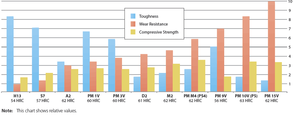
Toughness of tool steel is defined as the relative resistance to breakage, chipping, or cracking under impact or stress. Using toughness as the only criterion for selecting a tool steel, H13 or S7 (shown in the chart above) would be the obvious choice. However, all desired characteristics–and the needs of the job–must be considered when making your selection.
Tool steel toughness tends to decrease as the alloy content increases. Toughness is also affected by the manufacturing process of the steel. The PM (particle metallurgy) production process can enhance the toughness of the steel grade due to the uniformity of its microstructure.
Hardness also affects toughness. Any given grade of tool steel will have greater toughness at a lower hardness. The lower hardness, however, could have a negative effect on other characteristics necessary to achieve acceptable tool life.
Wear Resistance
Wear resistance is the ability of the tool steel to resist being abraded or eroded by contact with the work material, other tools, or outside influences such as scale, grit, etc. There are two types of wear damage in tool steels–abrasive and adhesive. Abrasive wear involves erosion or breaking down the cutting edge. Adhesive wear is experienced when the work piece material adheres to the punch point, reducing the coefficient of friction, which increases the perforating pressure.
Increased alloy content typically means increased wear resistance because more carbides are present in the steel, as illustrated in the chart.
Carbides are hard particles that provide wear resistance. The size and dispersion of the majority of carbides are formed when alloys, such as vanadium, tungsten, molybdenum, and chromium combine with carbon as the molten steel begins to solidify.
Greater amounts of carbide improve wear resistance, but reduce toughness.
Compressive Strength
Compressive strength is a little known and often overlooked characteristic of tool steels. It is a measurement of the maximum load an item can withstand before deforming or before a catastrophic failure occurs.
Two factors affect compressive strength. They are alloy content and tool steel hardness.
Alloy elements such as Molybdenum and Tungsten contribute to compressive strength. Higher hardness also improves compressive strength.
Tool Steel Benefits
- H13–54 HRC
- Popular hot work mold steel
- Good balance of toughness, heat check resistance, & high temp. strength
- Moderate wear resistance
- S7–57 HRC
- High impact resistance at relatively high hardness
- Very high toughness to withstand chipping and breaking
- A2–62 HRC
- Good toughness
- Moderate wear resistance
- Combination of properties and low cost make it well suited for a variety of tooling applications
- PM 1V–60 HRC
- Very high impact toughness
- High heat resistance
- Good wear resistance
- PM 3V–60 HRC
- High toughness
- Wear-resistant
- Maximum resistance to breakage and chipping in a wear-resistant steel
- D2–61 HRC
- High carbon, high chromium
- Good wear resistance
- Moderate toughness
- M2–62 HRC
- Tungsten-molybdenum high speed steel
- Very good wear resistance
- Good toughness
- PM M4 (PS4)–62 HRC
- Excellent wear resistance
- High impact toughness
- High transverse bend strength
- PM 9V–56 HRC
- Good toughness and wear resistance
- Resists cracking
- Not for applications requiring high compressive strength
- PM 10V (PS)–63 HRC
- Extremely high wear resistance
- Relatively high impact toughness
- Excellent candidate to replace carbide in cold work tooling applications
- PM 15V–62 HRC
- Exceptional wear resistance, second only to carbide.
- An alternative to solid carbide where carbide fails by fracture or where intricate tool design makes carbide difficult or risky to fabricate.
In-house Metallurgical Lab—Solutions-based Testing & Analyses
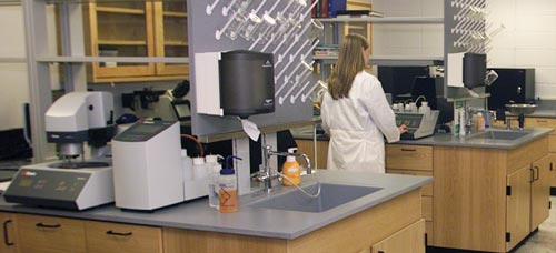
Dayton’s in-house metallurgy lab is designed to develop new products and to test and analyze the quality and viability of materials used in the manufacture of Dayton products. Laboratory services include: hardness testing; metallography (e.g., coating thickness); and failure analysis.

Equipment includes a high-resolution scanning electron microscope used to evaluate metal structures and a full complement of high-tech equipment used for specimen preparation, routine testing, microscopy, heat treatment evaluation, and failure analysis.
Metallurgical Services
- Micro Structure Analysis
- Stereoscopic Analysis
- Material Qualification
- Metallurgical Qualification
- Surface Treatment Analysis
- Conventional Hardness Testing
- Micro Hardness Testing
- Wear Analysis
- Failure Mode Analysis
- Scanning Electron Microscopy
Dayton’s metallurgy lab utilizes leading-edge equipment, employs professional, experienced metallurgists; and is the first full-service laboratory of its kind in the industry.
Heat Treating–Optimizing Tool Steel Properties
Heat treatment involves a number of processes that are used to alter the physical and mechanical properties of the tool steel. Heat treatment–which includes both the heating and cooling of the material–is an efficient method for manipulating the properties of the steel to achieve the desired results.
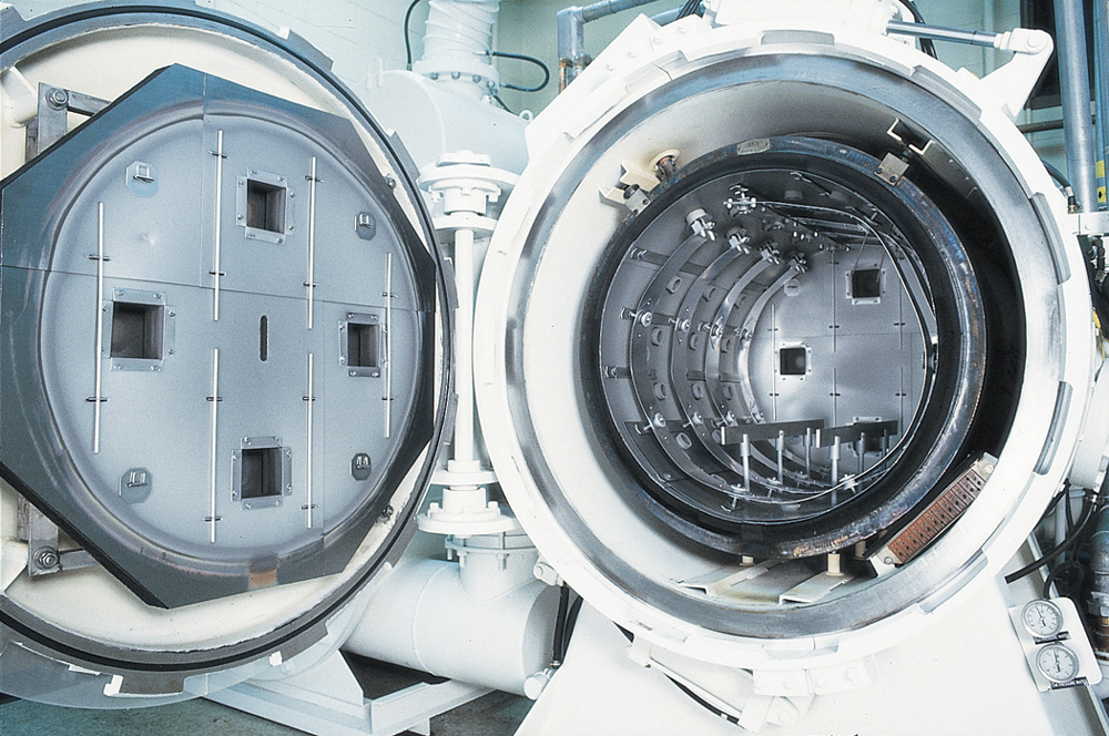
A vacuum furnace is used to heat the metals to very high temperatures and allow high consistency and low contamination in the process. Each grade of tool steel has specific heat treating guidelines that must be followed to acquire optimum results for a given application. Unlike cutting tools, the nature of the stamping operation places a high demand on toughness. Thus, a specific steel grade used as a tool steel for stamping must be heat treated differently than one used in a cutting tool.
Tool steel heat treatment processes include: material segregation; fixturing; pre-heating; soaking; quenching; and tempering. The following procedures are general guidelines for tool steel heat treatment. Certain steels require different timing, preheating and soaking temperatures, and number of tempers, e.g., M2, PM-M4, & CPM-10V.
Material Segregation & Fixturing
Segregation by size is extremely important because different individual sizes require different rates in preheat, soak, and quench. Fixturing ensures even support and uniform exposure during heating and cooling.
Pre-heating & Soaking
During pre-heating, both cold-work & high speed tool steels are evenly heated to prevent distortion and cracking. Soaking (austenitizing) is done for a specific time to force some of the alloy elements into the matrix of the steel.
Quenching
Quenching is the sudden cooling of the parts from the austenitizing temperature through the martensite transfer range. The steel is transformed from austenite to martensite, resulting in hardened parts.
Tempering
Untempered martensitic steel is very hard, but too brittle for most applications. Tempering is heating the steel to a lower-than-critical temperature to improve toughness. Tool steels are typically tempered at temperatures between 400° – 1000°F.
Cryogenics
Cryogenics is a process that aids in transformation of austenite to martensite, ensuring greater hardness results and reduced internal stresses. This process takes place at temperatures between -150° and -310°F and will vary in duration, depending on the size of the parts.
The Vacuum Furnace

- The process starts by removing the atmosphere creating a vacuum and electrically heating the parts in the hot zone.
- After the parts are properly heated (austenitized) the system is backfilled with nitrogen. Nitrogen is used as a means of conducting heat away from the parts. A large turbine blower forces room temperature nitrogen across the parts, cooling (quenching) them through the martensite transfer range.
- Hot nitrogen exits the hot zone through gates at the front and rear of the chamber.
- The nitrogen circulates through a heat exchanger where it is cooled.
- The cooled nitrogen is recirculated over the parts until they reach room temperature.
Dayton maintains a state-of-the-art heat treatment facility, including support equipment and systems monitored by our in-house metallurgist.

